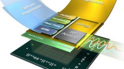
A multiplexer connects data from 2n inputs to the outputs, where n is a number of inputs selector. Generally, the multiplexer is written as mux and it is a digital switch. Example of this device is shown in Figure 1.
 Figure 1. Mux 2-1
VHDL code for the 2-1 Mux as written below,
LIBRARY ieee ;
USE ieee.std_logic_1164.all ;
ENTITY mux21 IS
PORT ( w0, w1, s : IN STD_LOGIC ;
f : OUT STD_LOGIC ) ;
END;
ARCHITECTURE watak OF mux21 IS
BEGIN
WITH s SELECT
f <= w0 WHEN ‘0’,
w1 WHEN OTHERS ;
END Behavior ;
or it could be written as other design using VHDL code as below,
LIBRARY ieee ;
USE ieee.std_logic_1164.all ;
ENTITY mux21 IS
PORT (w0, w1, s : IN STD_LOGIC ;
f : OUT STD_LOGIC ) ;
END;
ARCHITECTURE watak OF mux21 IS
BEGIN
f <= w0 WHEN s = ‘0’ ELSE w1 ;
END;